3RK 70mm 15W Micro AC Brake Motor
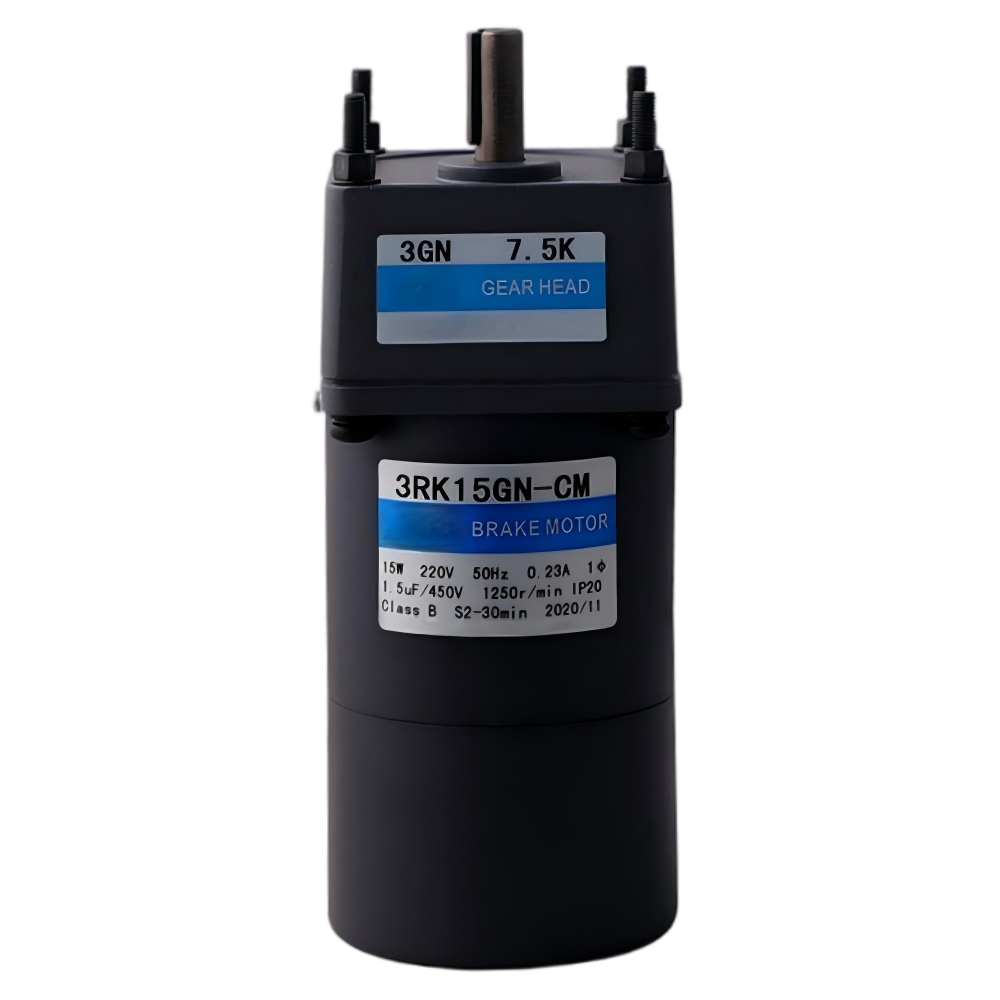
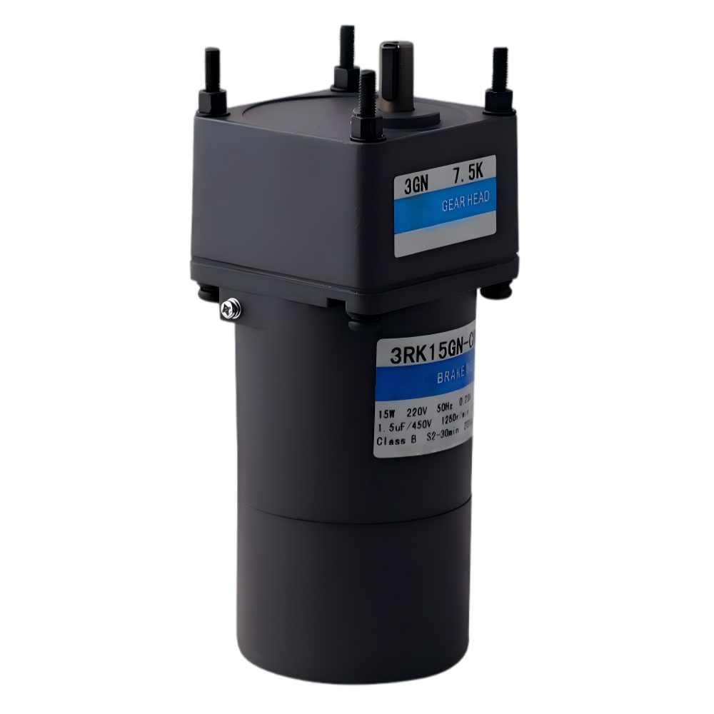
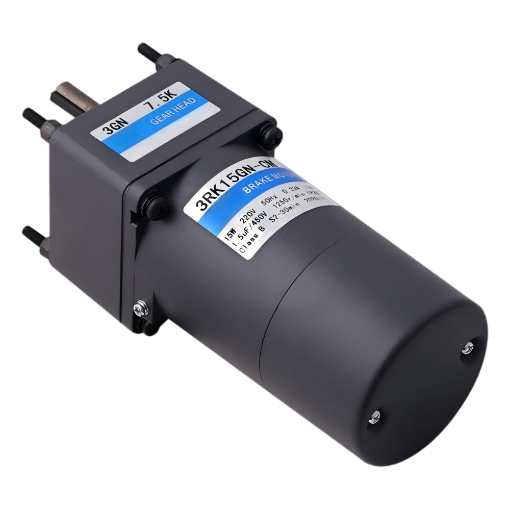
· High-efficiency Induction Core (Continuous Rating)
· Precision Ground Parallel Shaft Gearbox
· Reliable Class B Insulation & IP20 Protection
· Available in Single-Phase (110V/220V) & Three-Phase (220V/380V)
■ Motor Model Numbering System
| Item | Technical Specification & Meaning |
|---|---|
| ① Frame Size | 0: 42mm | 2: 60mm | 3: 70mm | 4: 80mm | 5: 90mm | 6: 104mm |
| ② Motor Type | I: Induction | R: Reversible | T: Torque |
| ③ Series | K Series |
| ④ Output Power | 40: 40W (Nominal output power wattage) |
| ⑤ Speed Control | R: Speed Adjustable | None: Fixed Speed |
| ⑥ Shaft Type | GN/GU: Pinion Shaft | A: Round | A1: Keyway |
| ⑦ Voltage & Poles |
A:Single-phase(1Φ) 110V 50/60Hz4P
B:Single-phase(1Φ) 110V 50Hz2P
C:Single-phase(1Φ) 220/230V 50Hz4P
D:Single-phase(1Φ) 220V 50Hz2P
E:Single-phase(1Φ) 110V/120V 60Hz4P
H:Single-phase(1Φ) 220/230V 60Hz4P
S:Three-phase(3Φ) 200/220/230V 50/60Hz4P
S3:Three-phase(3Φ) 380/400/415V 50/60Hz4P
T:Three-phase(3Φ) 200/220/230V 50/60Hz2P
T3:Three-phase(3Φ) 380/400/415V 50/60Hz2P
|
| ⑧ Accessories | T: Terminal Box | F/FF: Fan | M: Brake |
■ Reducer Model Numbering System
| Item | Technical Specification & Meaning |
|---|---|
| ① Frame Size | 0: 42mm | 2: 60mm | 3: 70mm | 4: 80mm | 5: 90mm | 6: 104mm |
| ② Pinion Type | GN: GN Type Gear | GU: GU Type Gear |
| ③ Gear Ratio | 50: Ratio 1:50 (10X denotes decimal gearhead 1:10) |
| ④ Bearing Type | K: Ball Bearing | KB: Ball Bearing for GU Square Case |
■ Specs Continuous Rating
| Model | Rating | Output power W |
Voltage V |
Frequency Hz |
Current A |
Starting Torque mN.m |
Rated Torque mN.m |
Rated Speed r/min |
Capacitor μF |
|
|---|---|---|---|---|---|---|---|---|---|---|
| Pinion Shaft | Round Shaft | |||||||||
| 3RK15GN-AM | 3RK15A-AM | 30min | 15 | 1ph 100 | 50 | 0.40 | 110 | 125 | 1200 | 7.0 |
| 60 | 0.56 | 105 | 105 | 1450 | ||||||
| 3RK15GN-EM | 3RK15A-EM | 30min | 15 | 1ph 110 | 60 | 0.43 | 85 | 105 | 1450 | 6.0 |
| 1ph 120 | 0.42 | |||||||||
| 3RK15GN-CM | 3RK15A-CM | 30min | 15 | 1ph 220 | 50 | 0.23 | 110 | 125 | 1200 | 1.5 |
| 1ph 230 | ||||||||||
| 3RK15GN-HM | 3RK15A-HM | 30min | 15 | 1ph 220 | 60 | 0.20 | 85 | 105 | 1450 | 1.5 |
| 1ph 230 | 90 | |||||||||
| 3RK15GN-SM | 3RK15A-SM | 30min | 15 | 3ph 220 | 50 | 0.14 | 220 | 125 | 1200 | – |
| 60 | 0.12 | 180 | 105 | 1450 | ||||||
| 3RK15GN-S3M | 3RK15A-S3M | 30min | 15 | 3ph 380 | 50 | 0.08 | 220 | 125 | 1200 | – |
| 60 | 0.06 | 180 | 105 | 1450 | ||||||
■ Allowance Torque Unit : Upside(N.m)/Belowside(kgf.cm)
| Type Motor/Gearhead |
Gear Ratio | 3 | 3.6 | 5 | 6 | 7.5 | 9 | 10 | 12.5 | 15 | 18 | 20 | 25 | 30 | 36 | 40 | 50 | 60 | 75 | 90 | 100 | 120 | 150 | 180 | 200 | |
|---|---|---|---|---|---|---|---|---|---|---|---|---|---|---|---|---|---|---|---|---|---|---|---|---|---|---|
| Speed r/min |
50Hz | 500 | 417 | 300 | 250 | 200 | 166 | 150 | 120 | 100 | 83 | 75 | 60 | 50 | 41 | 37 | 30 | 25 | 20 | 16 | 15 | 12.5 | 10 | 8.3 | 7.5 | |
| 60Hz | 600 | 500 | 360 | 300 | 240 | 200 | 180 | 144 | 120 | 100 | 90 | 72 | 60 | 50 | 45 | 36 | 30 | 24 | 20 | 18 | 15 | 12 | 10 | 9 | ||
|
3RK15GN-AM
3RK15GN-EM
3RK15GN-CM
3RK15GN-HM
3RK15GN-SM
3RK15GN-S3M
|
3GN□K | 50Hz | 0.30 | 0.36 | 0.51 | 0.61 | 0.76 | 0.91 | 0.97 | 1.30 | 1.50 | 1.80 | 1.94 | 2.30 | 2.70 | 3.30 | 3.48 | 4.10 | 5.00 | 5.00 | 5.00 | 5.00 | 5.00 | 5.00 | 5.00 | 5.00 |
| 3.06 | 3.67 | 5.20 | 6.22 | 7.75 | 9.28 | 9.90 | 13.2 | 15.3 | 18.3 | 19.8 | 23.4 | 27.5 | 33.7 | 35.5 | 41.8 | 50.0 | 50.0 | 50.0 | 50.0 | 50.0 | 50.0 | 50.0 | 50.0 | |||
| 60Hz | 0.26 | 0.31 | 0.43 | 0.51 | 0.64 | 0.77 | 0.80 | 1.10 | 1.30 | 1.50 | 1.64 | 1.90 | 2.30 | 2.80 | 2.88 | 3.50 | 4.20 | 5.00 | 5.00 | 5.00 | 5.00 | 5.00 | 5.00 | 5.00 | ||
| 2.65 | 3.16 | 4.38 | 5.20 | 6.53 | 7.85 | 8.16 | 11.2 | 13.2 | 15.3 | 16.7 | 19.3 | 23.4 | 28.5 | 29.4 | 35.7 | 42.8 | 50.0 | 50.0 | 50.0 | 50.0 | 50.0 | 50.0 | 50.0 | |||
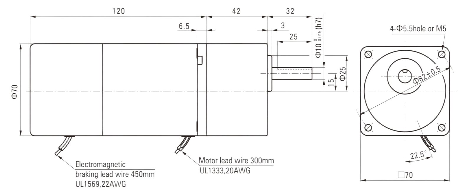
■ Dimensions (Unit mm)
■ Wiring Diagram
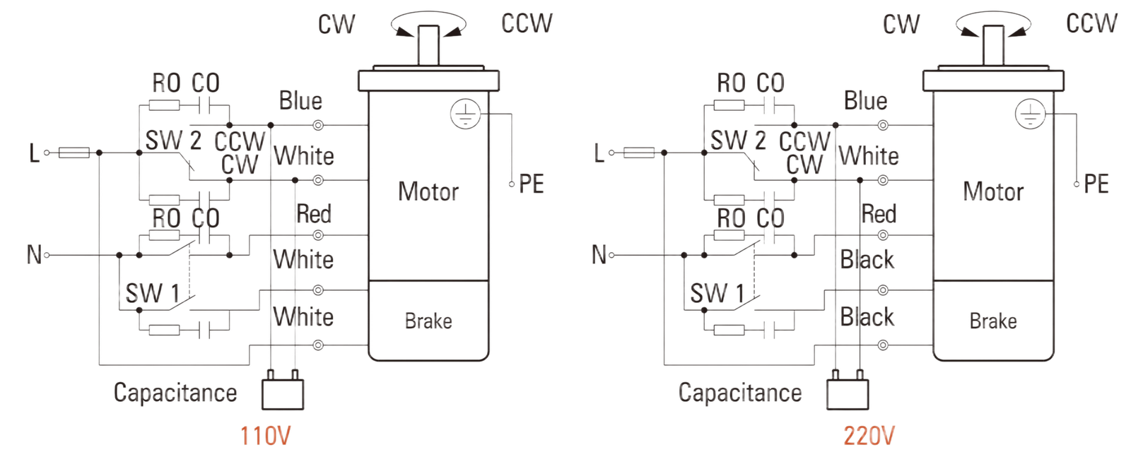
-SW1 operates both motor and electromagnetic brake action. (Switched simultaneously)
-The motor will rotate when SW1 is switched simultaneously to ON.
-When SW1 is switched simultaneously to OFF, the motor stops immediately with the electromagnetic brake and holds the load.
-If you wish to release the brake while the motor is stopped, set the SW1 to off and connection point at the side of black lead to ON.
Direction of Rotation.
To rotate the motor in a clockwise (CW) direction, turn SW2 to CW.
To rotate the motor in a counterclockwise (CCW) direction, turn SW2 to CCW.
| Switch No. |
Switch Contact Rating | Note | |
|---|---|---|---|
| Single-Phase 100V, 110/120V Input | Single-Phase 220V, 230V Input | ||
| SW1 |
AC 125V 3A minimum (Inductive Load) |
AC 250V 1.5A minimum (Inductive Load) |
Switched Simultaneously |
| SW2 | – | ||
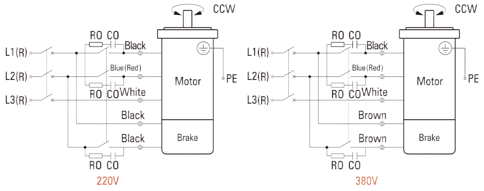
Direction of Rotation.
To change the rotation direction, change any two connections between R, S and T.
|
Switch No. |
Capacitor of Switch Connection Point | Note |
|---|---|---|
| SW1 |
AC 250V 1.5A minimum (Inductive Load) |
Switched Simultaneously |
■ Features For Power Off Activated Type Electromagnetic Brake Motor
1.Structure and operation principle
Table 3 is the structure for the electromagnetic brake motor. We produce the power off activated type. Exerting the voltage on the winding, it will magnetize the armature pressed by the spring. The motor will be in a stage of rotating, when there is a backlash between the armature and brake rim. Once the winding voltage is cut down, under the influence of spring, the armature press the brake rim, which will create a brake force. Then the motor gets to a stop.
2.The characteristics of the electromagnetic brake
It is an AC power off activated type electromagnetic brake which is connected directly with the motor. It will get to a blink stop and keep load when the supply is power off. It will keep the torque between 0.05~2.0Nm. It is especially suitable for the safety brake in the circumstance of unconsciously power off.The electromagnetic can change its direction frequently. It can be stopped 6 times in a minute. But be sure that it lasts for 3 seconds or more.
After we set a commutating loop in the brake, it can share the power supply with the motor.
※The value is standard. It will be change in different condition. When actually used, be sure to make the surface temperature of the motor less than 90°C.
3.The features for the starting time and brake time
The starting time means the time for the motor’s starting time plus the electromagnetic brake release time. The brake time means the time from power cut off to the time of motor completely stop. The over-run, starting time and brake time will be different according to the different applications.